
| Introduction:
Setting Up Your Transmitter Audio
This page was designed to step you through the several different aspects of setting up your
transmit audio from component ordering to individual processor settings necessary in achieving that ultimate eSSB audio that you have been
looking for. GRAPH 1 The broadcast AM station in white (WBBM AM in Chicago) above is producing 9.5kHz of audio via a 19kHz
RF bandwidth. (9.5kHz LSB + 9.5kHz USB plus carrier) This bandwidth supports excellent vocal and fair music reproduction. GRAPH 2 The SSB "Mid-fi" station (Cyan) sounded excellent! Not exactly like AM broadcast, but closer than the typical
SSB audio without being a full 6kHz wide. In fact, this station was about 3.5kHz wide. More importantly, the station was clean with excellent
carrier suppression and extremely low I.M.D. (Inter-Modulation Distortion) products. This actually contributes to less bandwidth overall
than some stations running a 2.4kHz bandwidth with poor I.M.D., sometimes making them as much as 10kHz wide! GRAPH 3 So, how do we improve our audio from GRAPH 1
to GRAPH 2 or GRAPH 3... Read on!
|
|
There are several possible connection schemes when connecting your rack audio together and interfacing
it to the transmitter. I will discuss the pros and cons of each below.
Audio Rack Connections: 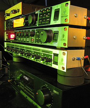 The best way to connect
your audio gear together is via the Balanced XLR or 1/4" TRS connectors on your gear, using premium Starquad cable. (See below
for Starquad wiring) This is not always possible however because some gear does not provide Balanced input and/or output
connectors. The best way to connect
your audio gear together is via the Balanced XLR or 1/4" TRS connectors on your gear, using premium Starquad cable. (See below
for Starquad wiring) This is not always possible however because some gear does not provide Balanced input and/or output
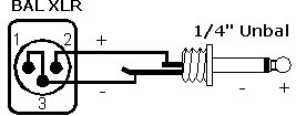
connectors.You could also use audio isolation transformers between each piece of audio equipment wiring them for balanced on each side. This would provide maximum ground-loop isolation preventing annoying hum and buzz while also providing great RFI immunity. However, this can be costly when using premium grade transformers like the ones made by Jensen. See this link: http://www.jensen-transformers.com/pro-audio/isolators/ - The next best way is to use Audio Transformers that can convert from Balanced to Unbalanced or vice-versa as mentioned above, in a system that cannot inherently be completely Balanced. Once again, transformers are a great way to convert these signals as well as providing for maximum isolation between devices. - In some systems, it may be advantageous to just use an unbalanced wiring configuration throughout the entire rack. The advantage to this, if not all the equipment has Balanced connectors, is that you don't have to worry about any Bal to Unbal (or vice-versa) conversion problems. However, a completely unbalanced rack will not have the Hum and RFI rejection advantages of a completely Balanced wiring scheme! - As a last resort, you can just simply wire for a Pseudo- Balanced connection as shown below in figure 2. While this is not the most eloquent way to unbalance a balanced signal, and there are some technical drawbacks by doing this, it will satisfy the basic requirements for an unbalanced signal. |
| Audio Cables / Wiring It is important to use good quality cabling and use the proper wiring techniques throughout your transmit and receive systems to keep hum/buzz and RFI to a minimum. If possible, you should use a twisted, 4-conductor, 95% shielded (or better) cable in a balanced configuration throughout your transmitter audio rack. This type of cable is known as "Starquad" and is available at many musical outlets for about 50 cents per foot. To properly wire a balanced to balanced cable using 4-conductor Starquad, assuming the wire colors are White, Blue and Silver, wire the cable as follows combining the same colors on one end with the same on the opposite end. If your cable colors are different, just use the same colors on both ends of the cable as shown in the following example: 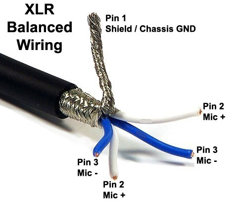
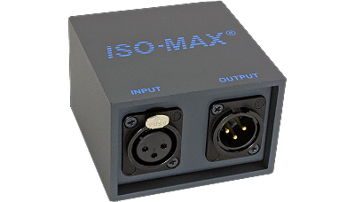
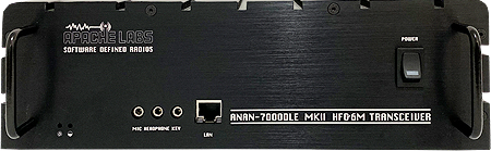
Interfacing the Rack to the Transmitter: One of the most important aspects of the wiring scheme is how to interface the audio processing rack to the transmitter. There are several ways to accomplish this. One important thing to remember is that you must pad the Line-Level signal down to a Mic-Level signal if you will be feeding the transmitters mic input jack on the front panel. A Line-Level signal fed into a Mic-Level input will result in distortion! You can use a 12:1 transformer to accomplish padding or a resistor network pad of some kind... But you MUST pad down the signal if using the mic input connector on your rig! If you will be feeding your rack audio to either a Balanced Modulator input or rear panel Line-Level Accessory input, then padding will not usually be necessary. Described below are some interfacing options... As in wiring the rack pieces to each other, the best way to interface your audio rack to your rig is accomplished by using an audio isolation transformer. This is true whether feeding your rig's balanced modulator, line input, or mic input. The most direct approach is the best! If you are using an analog transmitter, then feeding the Balanced modulator or line input (bypassing the noisy and frequency restricted mic amp) via a 1:1 transformer is the best way. If you are using one of the more recent SDR transmitters, then feeding the audio to the line input section in the transmitter via a 1:1 transformer is the best way to go for the same reasons mentioned above. JENSEN AUDIO ISOLATION TRANSFORMER SOLUTIONS: If your transmitter is equipped with a "line-level" input, I recommend the pre-made Jensen 1:1 PI-XX series of the "IsoMax" transformer box specifically for this application. This box receives a balanced line-level signal and sends a balanced or unbalanced line level signal out to the transmitter's line-level input and can be configured with a variety of input/output connectors. ($150 direct from Jensen) I use the Jensen PI-XR transformer (XLR bal in to RCA unbal out) and it's perfect for interfacing my audio rack to my ANAN's rear-panel RCA line input connector. https://www.jensen-transformers.com/product/pi-xx/
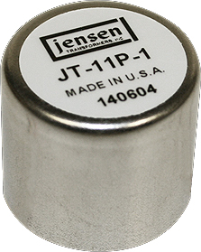
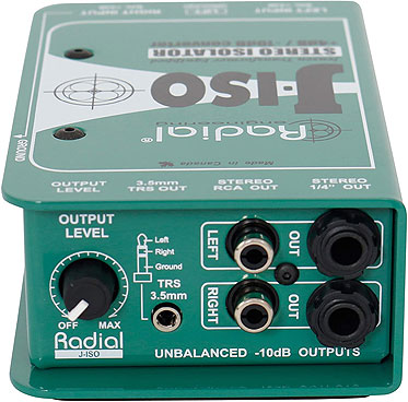
If you want to save a afew dollars, you could build your own box using a Jensen 1:1 Line-Level to Line-Levell audio transformer model JT-11P-1. (About $70 direct from Jensen) https://www.jensen-transformers.com/transformers/line-input/ If your transmitter does not come equipped with a "Line-Level" input, and you must use a mic-level input, I recommend the excellent Radial Engineering J-ISO Jensen Transformer direct-box specifically for this application. This box receives a balanced line-level signal and converts it to a balanced or unbalanced mic-level out. (About $250 from Amazon) (Click here to view)
See figures 6 and 7 in the "Transformers"
section below for Jensen line to Mic level transformer wiring. (Figure 3)
XLR Balanced Output to Kenwood 8 Pin Mic Plug with -40dB Balanced Resistor "H-Pad" Attenuator (For direct rack-to-rig, line to mic interfacing)  (Figure 4) XLR Unbalanced Output to Yaesu 8 Pin Mic Plug with -40dB Unbalanced Resistor "T-Pad" Attenuator (For direct rack-to-rig, line to mic interfacing) 
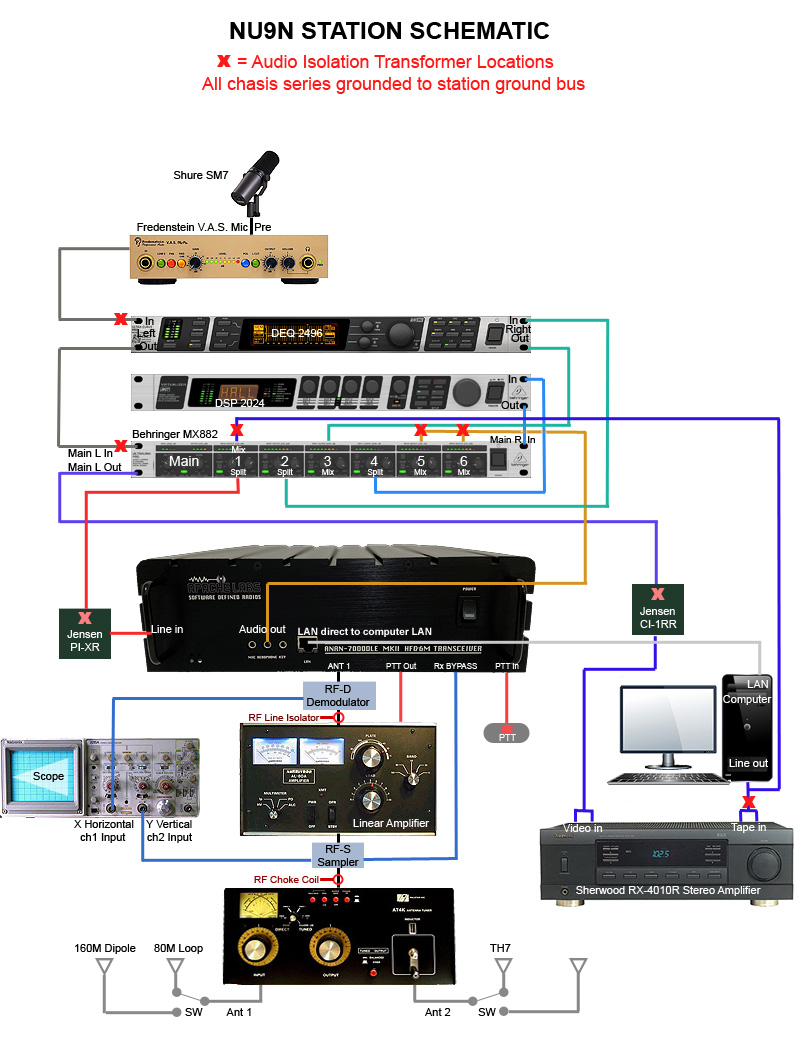
The graphic schematic below illustrates my wiring scheme after it is all put together...
|
|||||||||||||||||||||||||||||||||||||||||||||
|
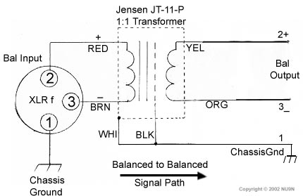
Audio Isolation Transformer Wiring Schemes (Figure 6)
(Figure 8)
 |

|
Improper leveling can either cause distortion or a bad signal to noise ratio. I wanted to cover this
issue first before getting into any of the individual processor setups. I have outlined below what I believe to be the best approach to leveling
your entire system. |
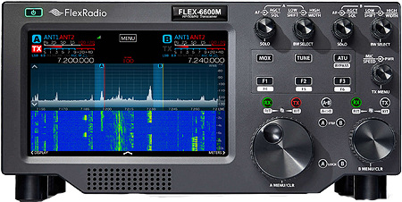
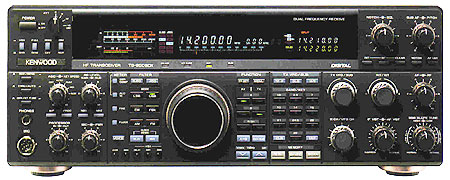
| Selecting a Transceiver Of all of the equipment in your audio rack, this one is key! The transceiver will be the deciding "Bottleneck" of what information will ultimately be transmitted. The old saying goes like this: "Your final audio will only sound as good as the weakest link in your audio system!" That "weakest link" IS your transceiver! All of your audio equipment will more than likely be capable of 20Hz ~ 20kHz in frequency response. Listed below are my recommendations for stock transceivers that can do a nice job:
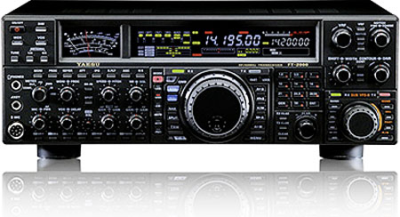
If you're into older traditional rigs, the Kenwood TS-950SDX and TS-850S with the optional DSP-100 are good and are capable of a bit wider transmit response than the rest. The Kenwood TS-850S with the optional DSP-100 has the best and most versatile transmit audio quality followed by the Kenwood TS-950SDX. I am definitely a fan of old Kenwood audio but buyer beware - There is not much support left for these old aging rigs and in some circumstances, parts are difficult or even impossible to find! Also, there has been a crop of offerings from Yaesu, namely the FT-2000 and FT-5000 that can easily accomplish 4.5kHz of transmit bandwidth with no effort. These rigs sound decent with just a decent microphone attached. But the new SDR's are king when it comes to features and capabilities. It should be possible to perform these mods to most analog transceivers with similar filters changes and a direct Balanced Modulator Feed to produce similar results. It all depends on the bandwidth of the filter you use and an appropriate carrier set point alignment. |
| Suggested Audio Components The following suggestions are just that, suggestions only. However, if you are price conscious, like me, these components will deliver excellent quality and a good "Bang-for-the-Buck"! My personal picks are as follows: Click on a picture for website
|
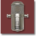
| Component Ordering Audio component ordering is important! First I'll recommend the ordering and then explain why. Microphone Microphones
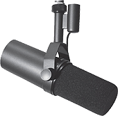
The first item in the chain is obviously the Microphone. There are three major types of microphones available. Dynamics, Condensers, (large and small) and Ribbons. While choosing a microphone type is a personal preference, I have found that "Dynamic" type microphones seem to work best for amateur radio and broadcast applications for a few reasons. First, because of the design characteristics of dynamic mics, they are not as susceptible to background noise as their condenser and ribbon counterparts. (FYI: Ribbon mics are "Bi-Directional") Also, dynamic microphones tend to be more "directional" in their pickup pattern that help suppress unwanted sounds from the adjacent sides of the mic. Finally, dynamic microphones have a much lower sensitivity and output than condensers making them inherently quieter in a noisy room. There are many operators who use condenser microphones successfully, but dynamic mics are still the best for amateur radio eSSB audio in my opinion. Microphone Preamp (Converts "Mic-Level" to "Line-Level" Signal)
Your microphone signal will need to be amplified to a "Line-Level" signal (about +40dB) before
it can be fed into a line-level device input such as an equalizer or compressor. Compressors require appropriate signal levels to compress
correctly.
Even though an equalizer can be fed with an un-amplified mic-level signal, the "signal to noise" ratio would suffer substantially. The internal "Op-Amps" in the EQ would not run at their designed specifications. Also, if you are using a condenser type mic, it will require "Phantom Power", usually 48 volts, to power the mic transistors. Noise Gate (Optional) This is usually the best place to insert a dedicated noise gate. The reason being that a noise gate has more dynamic range to work with since it appears before the compressor. After compression, there is little dynamic range left to distinguish between voice energy and background noise energy. Also, you will kill background noise up front before it is EQed and compressed. So, if a dedicated gate is used, insert it just after the preamp and before any EQ or compressor. Soft Compression (Optional) If you have a spare compressor, you could use up front in the chain to provide some soft compression before anything else happens dynamically. A ratio of about 4:1 would be plenty and would provide some headroom for the processing that will follow. Spectral Enhancers (Optional) (Aphex 104 Aural Exciter / Behringer EX3200 / BBE Sonic Maximizer) These processors were designed to bring life to old lifeless recordings that lacked bottom and top end fidelity. They do this in a very interesting way by actually creating even-order harmonics in the audio that produce resonance in the lows and highs. To some, this may seem like a "Voodoo" approach to processing audio, but it can be very effective at producing low and high end resonance, if that is what you are looking for. Spectral enhancers should be understood as "Harmonic Coloring" devices that attempt to bring more of a pleasing tone to the voice or music source. Note: In our application of Amateur Radio audio, spectral enhancers should only be used for polishing already good sounding audio. They were never intended to be a stand-alone device in establishing your sound. You should be able to produce excellent audio characteristics without any spectral enhancement at all! Over-use of a spectral enhancer will sound too thick and boomy on the low frequencies and will sound like a very shrill buzz-saw effect on the high frequencies. Use these devices with caution remembering that a little effect goes a long way! Equalizer This would be my choice for the placement of the next component. The reasons I would place the EQ
BEFORE the compressor are as follows:
If the EQ were placed AFTER the compressor, high frequency energy from the EQ would be able
to distort the audio since the compressor would not see it, therefor not being able to react to it.
With the EQ BEFORE the compressor, we can cut midrange frequencies from influencing the compression action of the high frequencies before it gets to the compressor. And, if the compressor has a built in low frequency filter preventing the lows from influencing the compressor, we have an elegant solution where we can adjust the compressor so that ONLY high frequencies will be limited aggressively, while the low and midrange frequencies will be compressed conservatively. Compressor / Limiter / Noise Gate or Downward Expander The Equalizer / Compressor order was discussed above. Notice that I have the compressor BEFORE the effects processor. The reason for this is because most compressors on the market these day have built-in noise gates. In fact, the majority of compressors have three processors built in, usually in this order: Noise Gate > Compressor > Peak Limiter A noise gate or downward expander placed AFTER an effects processor would destroy the effects tail on the audio and would sound chopped off! We want to do the gating BEFORE the effects so that when the gate closes, the effects will still linger as long as you keep the PTT switch closed and not be chopped off prematurely. If you were running a separate Noise-Gate, I would suggest that it would be placed right after the preamp. If you don't want to spend the extra money on a separate gate, those built into compressors do an adequate job. If you will be using a dedicated noise gate just after the preamp as discussed above, you will probably not want to use the built in gate in your compressor. If you do not have a dedicated noise gate after the preamp, then this would be the next best place to have it working, although it will not be as effective as it would be just after the preamp for reasons mentioned above. De-esser Many manufacturers include a "De-Essing" feature in their processing, designed to tame high frequency dynamics that can cause distortion or uneven high frequency content. De-essers are dynamic rather than static in the way that they process high frequencies. While de-essers can be a handy tool in your audio processing arsenal, they are limited in scope to just a single band of operation. A more elegant approach would be the use of a "Dynamic EQ", where several frequency bands of dynamic control can be assigned at once. The Behringer DEQ2496 is such a device and takes care of high frequency processing beautifully! Effects Processor (Optional) Usually, you want the effects processor as the last piece. This puts the final polish on the audio, such as a virtual room effect, or perhaps some plating or mild reverb. Since the effects processor will not noticeably add or subtract any frequency content, the already processed signal should still be okay for the final transmission through the transmitter. Audio Level Processors (Not Recommended for Amateur Radio SSB) Aphex Dominator 720 / Compeller 320A / etc... These devices are designed to insure constant output leveling. If you want constant "full duty cycle" type of output, then these devices help achieve this. In AM broadcast applications, these devices are essential. They keep the output constant and loud! However, I have found that these devices in our applications do nothing more than increase background noise and work your amplifier harder than necessary. I feel that it is better to have a good directional antenna system where the RF dB's count more than any external audio "Duty Cycle" processing. In our application, it seems that SSB fidelity and heavy duty cycle processing do not mix well for various reasons. All that is needed is some moderate compression and perhaps some peak-limiting. Leave the heavy Audio/RF leveling for broadcast AM applications and keep your SSB Hi-fi audio processing to a minimum for a more natural and transparent effect. Multi-Function AM/FM Processors - Orban, Omnia, etc... (Optional) These processors are commonly used in broadcasting and audio production studios where workable bandwidth are 6kHz and beyond. While these devices are excellent in what they are designed to do, their application for Amateur Radio eSSB is not specific enough unless you are transmitting at 6kHz of audio bandwidth or more. Their flexibility is very limited below 6kHz bandwidths and tend to focus better with wider bandwidths and professional RF equipment. These processors are best suited for AM and 6K+ eSSB operations where agressive talk-power and audio density is desired. Personaly, I'm not a big fan of this type of processing because they tend to add some distortion to the final audio as well as robbing you of what little dynamics you have left after all of the other dynamic processing in the chain. Mixer A mixer can be a great tool if you plan on combining several signals together to be routed to your transceiver, or if you want to split several signals to other devices from a single source. For example, you may have the need to combine your audio output from your rack with the out put from a recording device, or perhaps from two or more audio chains to be routed to your transceiver. You may also need to combine audio outputs from several rigs to a signal input to a stereo amplifier for better receiver audio reproduction. There are several mixers available, from simple to elaborate, from cheap to very expensive. I have found that the low cost mixers, such as some of the Behringer models, work just fine for our applications. I especially like the Behringer MX-882 for its versatility in not only mixing but splitting signals as well. It's a one-rack space unit and can also level your line source to mic levels suitable for direct input to your transceiver's front panel mic input connector. And, it's only about $100. Most of the Behringer mixers are quite affordable and should provide you with enough features to accomplish your particular needs. A Final Thought In the big scope of things, find what works for you! Not every processor will work for your particular application. By all means experiment and find what works and what doesn't. You will eventually find the best processing for your needs. The suggestions above are based on my experiences and not anything that should be considered as bible. Have fun experimenting while dialing in your ultimate sound. |
|
Mic Switches Microphones vary greatly of course. Some have switches on the case that can roll-off bass frequencies and boost high frequencies. I would recommend placing all switches in their widest positions so that the bass and treble from the microphone is is not held back. If you need to cut some bass, do it on the EQ! It's better, I think, to let the EQ do the job of EQing and not restrict the mic in any way. If you do restrict the mic, you may not be able to recover it properly later on if needed. Mic Placement Mic placement may vary depending on what kind of mic you are using. For Dynamic mics, you should be about 2 to 4 inches from the front and maybe slightly angled away to prevent "Popping". The beauty of dynamic mics is the insensitivity to background noise and their directivity, as compared to condenser types. Just experiment to see what works best for you. Condenser mics are much more sensitive and require you to extend your distance to anywhere from six to a full twelve inches away! Be careful... These babies are sensitive and background noise can be an issue! Mic Pop Filters There are two types of Pop Filtering on the market. The first is a simple "Sock" that fits over you mic. The second and more effective filter is a specially made mesh screen that is circular, flat and is positioned in front of the mic, via a separate adjustable boom. The mesh screens are typically more transparent with high frequencies than the socks and are a better choice in my opinion. Mic Support System There are several types of mic support systems available. The Inno heavy duty, fully adjustable boom arm is an excellent choice! It sells for $60.00 and is a real bargin! To see this product, click on the following link or point your browser to: https://www.amazon.com/InnoGear-Microphone-Suspension-Adjustable-Snowball/dp/B07DHLSTLV?th=1 |
|
Input adjustment: The mic input control should be adjusted so that the clip led only flickers occasionally. This would be about the equivalent to 0dBu on an analog VU meter. The reason we want maximum VU levels here is to optimize the Signal-To-Noise characteristics. If you experience high levels of background noise because of high VU levels from the preamp to the compressor, it's usually because the compressor "Threshold" level is set too low. See the "Gate/Compressor/Limiter Setup" section below. Output Adjustment: The output control should be adjusted to drive the input of the next component at about 0dB. If the next component is a digital unit, then you may want to decrease this to around -3dB. Tips: Warm vs. Clean If you are looking to your preamp to produce a warm sound up front, then you will want to set the preamp input control a little high and the output control a little low. If, on the other hand, you are looking for your preamp to produce the cleanest sound possible, then set the input control a little low and the output control a little high. Experiment a little to find what settings sounds best to your ears. |
|
The equalizer is definitely the most important piece of equipment in your audio rack! Most transceivers do an excellent
job of passing all the midrange frequencies between 300Hz ~ 2.5kHz usually with an added dominance between 500Hz ~ 800Hz. Unfortunately, most
stock transmitters roll-off the bass frequencies below about 100Hz and down, as well as the high frequencies above about 2.7kHz and up unless
you are using a modern SDR. With ALL rigs, we need to do basically four things:
As you can see, I had to boost the Low and High frequencies by 8dB, and cut the mid frequencies by -22dB resulting in a difference of 30dB The resulting Kenwood TS-850S/DSP-100 transmitted audio is represented below in its full bandwidth: (Note: Do not try this with a transmitter that can not produce 6kHz naturally or severe filter blow-by will occur.)
The "Behringer DSP1100 Setup Page" link below was designed to accommodate 1100 users, but
the EQing principle is applicable for all EQ's.
Click here to view the Behringer DSP1100/1124 setup page A final note: Set up your EQ before you setup your Compressor. Get the sound you are looking for and ignore any distortion you may hear in your monitor or second receiver. You can address that later as prescribed in the compressor setup section. As an aid to help you see what happens with EQing and too much of it, refer to the tables below: ( EQ Information source: Alesis )
This next table may be used as an aid to determine the -3dB points of the lowest and highest roll-off frequencies when the Center frequency and Q factor or octave range is known. To convert Octaves to Q, consult the chart below.
This last two table are excellent resources. The first developed by Bell Laboratories, courtesy of AE4FB, is used to determine the desired Low or High frequency -3dB amplitude points based on the bandwidth of the signal to insure even distribution of high and low frequencies based, I'm amusing, on a 3dB/Octave distributed amplitude decline across the entire spectrum of available frequencies.. The second is a modification of the first assuming a -1.5dB/Octave distributed amplitude decline, instead of -3dB/Octave, across the entire spectrum of available frequencies, thus dividing the formula by half. This one will produce a much more robust low end and have a smoother sound.
|
||||||||||||||||||||||||||||||||||||||||||||||||||||||||||||||||||||||||
|
The audio compressor, in my opinion, is the second most important piece of equipment in your audio arsenal. A poorly
adjusted compressor will either sound too "Squashed", or not properly limit frequencies that will cause distortion at the transmitter.
You may also experience heavy background noise due to an improper setting of the Threshold control. We really only need just enough compression/limiting
to get the job done and no more. With the settings of your Threshold, Ratio, Attack and Release, you should be able to compress and limit effectively
and transparently. Compressor: If you have a separate Limiter section, then you can be less aggressive with your compressor. I would recommend the following settings for some mild compression: Mode: Manual Ratio: 2:1 Attack: 10mSec Release: .5 Sec Threshold: Adjust for about 3dB of Gain Reduction Don't get carried away! We just want to control the peaks and add a little boost (3dB) to the final output. A 3dB boost will effectively double the sound of the audio! CAUTION: A final note about the compression "Threshold" setting: If you experience high levels of background or room noise, it is most likely the result of over compressing. This is NOT caused by high input/output leveling, but rather by too much signal being processed by the compressor via the threshold level control. Again, we only want to adjust the compressor threshold so that normal speech produces about -3dB of gain reduction. The high frequencies will be compressed more aggressively, but most room noise will fall in the area of 30Hz ~ 600Hz, so high frequency gain reduction is not a factor. If the compressor/limiter has been set up correctly, the Bass and Midrange frequencies should produce about -3dB of gain reduction, and the high frequencies (2 ~ 5kHz) should produce about 10 - 15dB of gain reduction. Peak Limiter: If you have a separate peak Limiter circuit, it is usually the last module in your processor. Adjust it so that the loudest peaks do not exceed the absolute maximum output that you want. Output Gain: If this will be last processor in your rack before the transmitter, then after all of the above modules have been adjusted, adjust the output gain of your Gate / Compressor / Limiter so that you are back to the original ALC level that you established in STEP 1 of the "Level Adjustments Setup" section. If you will be using an effects processor after the compressor, then adjust the output gain for about -3dB and continue with the Effects Processor Setup. |
|
Effects Processing Effects processors can add a final polish to your hard earned audio, making it sound somewhat bigger and brighter with more effervescence as opposed to dry and lifeless. Adjusted properly, the effects should add a very subtle liveliness and slight sustain to your high frequencies. The desired effects that you want is a personal preference, but I would like to suggest a few things about effects setup that I believe sound the best. Reverb vs. Echo I often hear effects that sound more like an echo or bathroom than a reverb. This can occur when the initial signal delay is too long in time and is usually the result of selecting a small room effect. An echo sounds like the original signal being repeated one or more times within a given time frame. It sounds more like multi-path propagation than a concert hall. This is common in the CB world and in my opinion sounds horrible. A true reverb effect, on the other hand, sounds more like a smearing and continuation of the original signal giving the effect of a large room or hall where the signal gradually decays in a very smooth transition. So try initially selecting a large room or concert hall effect and work out the details from there. A Cleaner Sounding Reverb Effect All too often, I hear effects out there with way too much midrange and bass reflection, resulting in a very boomy and muddy sounding midrange in the final sound. This is not a desirable sounding reflection in my opinion. A great sounding reflection is one that highlights your high frequencies and not the low to mid frequencies as much. This can be accomplished easily by using the internal EQ of your effects processor. Set your effects processor's high frequency EQ to maximum, and your effects processor's low frequency EQ to minimum. By setting up your effects processor's EQ in this way, the high frequencies will be the only segment of your audio bandwidth with reflections. The result will be a very clean and lively sounding high frequency effect without all of the low and mid frequency muddy sounding reflections. Inline vs. Side-Chaining The absolutely best way to apply your effects processing is via a "side-chain" path rather than "inline". Every time your audio passes through a piece of equipment, there will be more degradation, artifacts, noise, and coloration added to the original audio. For this reason, it is best to "mix" your effects in a separate path from the main audio chain. In other words, your main audio path will NOT pass through the effects processor at all! The effects only will be mixed in separately and in parallel via a separate channel in your mixing console. This is referred to as "Side-chaining" the effects. For detailed information on using your mixers side-chain, consult your mixer owners manual. Effects Level How much of the effects should we mix in with the dry signal? Not much! I have found that the best effects level is one that isn't even noticed until you turn it off! No more, no less. Effects are just a way to put a final polish on our high frequencies without anyone really noticing the effects themselves. We want to draw attention to our voice, not our effects! So be careful not to add too much of a good thing. For a nice effect, try a thin or light "Plate" or a medium room program. Again, experimentation is key. Find what you like! Some Initial Settings to Play With Here is a profile created by Greg, W5UDX, for the the Behringer DSP-2024P with the following "Plating Reverb" parameters: Effect Button: PLAT Edit A: PRE.D = 0.010 Edit B: DECA = 2.358 Edit C: DAMP = 10 Edit D: SIZE = 33 Edit E: SHV.D = 32 Edit F: DIFF = 20 EQ Low: BASS = -16 EQ Hi: TREB = +16 MIX: 6 to 9 (User preference if using the DSP2024 inline in "INTN" mode) Here is a modified version of Plating using the Behringer DSP2024 that I personally use, with just a little less reverb length and depth: Effect Button: PLAT Edit A: PRE.D = 0.010 Edit B: DECA = 1.542 Edit C: DAMP = 15 Edit D: SIZE = 10 Edit E: SHV.D = 20 Edit F: DIFF = 20 EQ Low: BASS = -16 EQ Hi: TREB = +16 MIX: 7 to 10 (User preference if using the DSP2024 inline in "INTN" mode) Notes: Make sure the DSP2024 is set to "Mono" mode. (Press "Setup" then turn "INPUT" knob to "MONO".) I also recommend using the DSP2024 in a "Side-chain" configuration where you can mix in the desired effect in a separate channel of your mixer. If using the DSP2024 in a sidechain, make sure to set up the DSP2024 in "EXTN" mode instead of "INTN" mode. (Press "Setup" then turn "OUTPUT" knob to "EXTN".) |
|
Turn off any internal transmitter EQ or Compression. Let your external EQ and Compressor do this. Whatever
transmitter you are using, set it up for the maximum transmit bandwidth possible. In the future, I will update this "Transmitter Setup" section to include as many transceiver specific setups as I can. If you would like to contribute to this with a setup of your radio to include in future versions of this page, please send me an e-Mail with your setup data, menu settings, etc... Please submit to: John@nu9n.com |
|
"Do I Hear an "eSSB" Carrier?" There are evidently some folks on the air who have been reporting that some of the "hi-fi" guys have a carrier in their audio as a result of their wide bandwidths. I just want to briefly address this issue and discard any notion that this is happening as a result of any external or internal processing, bandwidth or any low frequencies below 80Hz that are being fed to the transmitter. When an SSB station has a relatively wide audio response and is modulating frequencies at or below 100Hz, an interesting phenomena takes place. When tuning off-frequency on such a given station, the listener may perceive what he/she thinks is a carrier. For example, if you are listening to someone on USB, and tune down frequency by about 500Hz, if the transmitting station is modulating 100Hz with any energy, then you will hear apparent tones at 600Hz. But, ONLY when they are talking! This is NOT a carrier that is being heard, but the 100Hz tone in the voice being off-beated up by 500Hz resulting in 600Hz tones via modulation. The reason that this phenomena is not usually noticed as much on the average narrow-band SSB signal, is because there is not enough low frequency energy to bring up to a higher pitch to start with. Just in case some believe that hi-fi audio effects a transmitter's carrier suppression, that's a hoax! The audio that you feed to the transmitter has NOTHING at all to do with the carrier suppression adjustments in a transmitter, especially with the newer DSP controlled rigs! If a hi-fi station keys the mic but does not talk, and their background noise is suppressed sufficiently, you should hear no carrier sounds at all. If you do hear a carrier while they are not modulating, then they may have a carrier suppression problem. But that is a totally separate issue from their audio being fed to their transmitter. A transmitter carrier suppression problem will still be evident even if the mic input signal is disconnected! Most modern DSP controlled transceivers like the Kenwood TS-950SDX,TS- 870S, TS- 850/DSP-100, Icom 756 Pro, Yaesu FT-1000MP etc... have transmitter carrier suppression figures better than -60dB or more! Speech is a complex thing… Human speech, as generated by the vocal chords, is very rich with harmonics. The way that vocal chords vibrate with passing air makes for interesting viewing on a spectrum analyzer. Of course, the vocal chords are not the only component to speech… There is also the changing shape of the mouth, producing the various vowel sounds, as well as air passing between the top of the tongue and roof of the mouth producing the high “hissing” sounds heard in “S”, “T”, and “CH” consonants. We shouldn’t forget the “P” sounds produced by little explosions of air between the upper and lower lips… All components of speech. However, for this discussion, I will just be focusing only on low frequency tones produced by the vocal chords themselves. SSB Only! When a voice is listened to on Single Sideband that has been properly tuned on frequency (zero beat), all is well… Just as it would be if listening in the AM or FM modes. However, if miss-tuned, where voice pitch is raised slightly (up frequency on LSB, or down-frequency on USB) something rather interesting happens as a result of the mistuning. This strange mistuned phenomenon ONLY happens in the Single Sideband mode! It cannot be reproduced with external audio pitch shifting devices or by speeding up a recording… Only in SSB… Why? It has to do in part with how Single Sideband is processed and filtered in the RF/IF/AF stages of a receiver, and how we are trained to listen in respect to low, midrange, and high frequencies in context. When audio pitch is raised as a result of mistuning (accelerated), the lower frequency contents of the vocal chords are also raised. This phenomena is present on ALL mistuned SSB signals, but is much more pronounced when the transmitter station has good low frequency response, well below 100 HZ. Example: Let’s assume that someone with a low rich voice is using a transmitter with good frequency response down to about 50 Hz. Let’s also assume that the low-frequency content of that person is prominent from 60 Hz. to 100 Hz. Now, you purposely mistune this person by raising the pitch of your receiver by 300 Hz. What you now hear are his bass components being remodulated and heard at 360 Hz. to 400 Hz. Instead of sounding like bass, it now sounds like lower midrange tones wobbling around as they speak! Because lower frequencies of the voice are more prominent than the upper frequencies of the voice, (by 80%) the remodulated bass tones will sound separate and raised in volume over the upper frequency components of the voice. This will give an illusion of separation between the two that you never noticed before. This is because of how we listen to normal speech. With normal speech, we reference and interpret the bass, midrange, and high frequency components of speech in a certain way that we accept. If we shift all of these frequency ranges up by 300 Hz., we have now moved the bass components of speech up into the midrange area of our hearing. Now we interpret it much differently than what we are used to. Since we have effectively removed the bass component of speech by raising it to the midrange area, our brain interprets the tones as being incorrect information. Bass components of speech do not belong in the midrange area of speech! So every time they talk, you hear these base tones remodulated into the lower midrange area of your receiver and of your hearing, along with the other components of speech that are also present.. Notes: This phenomena will be most prominent if the transmitting station has good low-frequency response to begin with, and low-frequency energy in the source voice. ALL receivers (wide or narrow) will hear the phenomena because all receivers can hear remodulated frequencies above 300 Hz. easily! As mentioned earlier, ALL mistuned SSB signals will exhibit this phenomena to some degree and can be heard if you listen carefully – Even female voices, with little low frequency energy, will exhibit this phenomena! In fact, women are the easiest for me to tune in because of this fundamental rule of listening; “They only sound harmonically normal at one specific frequency and not normal anywhere else." On the other hand, the hardest signals for me to tune-in correctly are men with very low voices, but with no bass content below 100 Hz. in their transmitted audio response. It drives me crazy to get their frequency right because they can actually sound harmonically normal on several specific frequencies! So in this case, a critical low-frequency reference is missing that would significantly aid in the proper tuning of a signal. How about that—eSSB can be a necessary evil after all!, HI. Bottom Line Basically, all you are hearing with this phenomena are low frequencies, remodulated to midrange frequencies, and then mentally interpreting bass as midrange. It’s very awkward… as it should be. Even though eSSB transmissions do occupy more bandwidth, it is not the upper frequency bandwidth that is the cause of this phenomena. This phenomena is only caused by vocal energy in the lower bass range below about 100 Hz. So extended high-frequency bandwidth has nothing what so ever to do with this phenomena. |
| Troubleshooting R.F.I. 60Hz Hum & Buzz You've connected your audio gear, set it up, tested it into your dummy load and are ready to present
your hard earned delicious audio to the world. You flip your switch from dummy load to antenna, key up and...... Whooooooow........ what was
that?
Radio Frequency Interference like crazy! If there is one thing that will drive you absolutely crazy, it's RFI. Hum and Buzz are easier to cure, but can still prompt you to get out a bottle of the Extra Strength Excedrin! Look at some of the following sections and see if there is anything you may be able to do that you're not doing currently to prevent RFI or Hum from letting you enjoy your audio. Don't worry, I've been through the RFI scenario and can tell you with confidence, there IS a solution for it. Determining the solution may take a bit of research, but it can be dealt with! Antenna Orientation: If your antenna is relatively close to your operating position, your battle with RFI may be a difficult one! The further you can get your antenna(s) from your shack or vice-versa, the better! Of course, this may not be the most practical solution in your unique installation, so below are some general suggestions to resist the strong RF fields already present in your shack. But if possible, steps should be taken to minimize the RF entering your shack at the source. Grounding: A good RF earth ground is worth it's weight in gold when it comes to a clean transmitted signal. Unfortunately, some of us do not have the luxury of having a true earth ground only 4 ft. away and/or good ground conductivity. The following, is a summary of some basic grounding guidelines:
Building an Indoor Counterpoise: (The following text is from the Radio Works catalog)
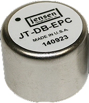
"If you cannot get close enough to earth to run a very short ground wire and install a good quality ground system, try a counterpoise. An easy example of a counterpoise is the ground plane used with vertical antennas when they are mounted high in the air." "In its simplest form, a counterpoise can be a single wire, one-quarter wavelength long or just slightly longer. For best results, a separate wire is required for each band. If you really want to get elaborate, use two or more wires routed in different directions to make up your counterpoise. The wires for different bands may be close together, insulated and routed in a convenient way around a room." "You can probably eliminate counterpoise wires for bands that are harmonically related in odd multiples. 15 and 40 meters or 80 and 30 meters are examples." AC Line Isolation: Use a good AC power strip with RFI/EMI/Surge and Isolation built in to distribute your AC power. Also, get your AC power from ONLY one AC source. Do NOT use multiple AC circuits, or AC ground loops will develop. The Triplite "Isobar" AC strip seems to work well. Audio Cabling: For maximum RF rejection, use high quality double-shielded, low capacitance twisted 4 conductor "Starquad" audio cable for all of your audio and speaker connections. Transmission Lines: Use high quality COAX with your antennas that use that type of transmission line and check your station jumpers from time to time for bad connections. If you will be using 300 or 450 ohm transmission line, and it enters your shack to your tuner, you may be dealing with RF entering via this route. Some hams use a remote Balun at the end of their balanced transmission line that terminates to coax just before entering the shack, helping to reduce RF entrance. Shielding Unshielded Cables: If you have any rotor control or AC line cables that are not shielded, you can wrap aluminum foil around them to help keep RF out. W5GI has reported that wrapping steel wool around these types of cable is also very effective. Audio Isolations Transformers: For absolute isolation between all audio components that ultimately break up the ground loops, use audio isolation transformers between every piece of audio equipment including one between the audio rack output to the transmitter mic input. Not only will this break up the ground loops, but also keep 60 cycle hum to a minimum... (-120dB). And as an added bonus, it will keep RF out of the signal path by presenting a very high impedance for RF while transferring your audio signal through the chain. I use the Jensen JT-DB-E for my interface between my rack and the transmitter mic input. They work great! The following link will navigate you to this site:. http://www.jensen-transformers.com/pro-audio/isolators/ RF Chokes: If needed, choke all of your RF and AF inputs in the system. "Mouser Electronics" (as well as others) makes a variety of toroids for all of your cable needs. What usually works the best for Amateur Radio HF applications and frequencies are the following:
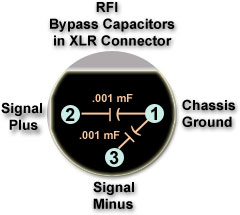
Bypass Capacitors:
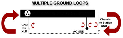
1) Use an Audio Isolation Transformer to break the XLR GND path between all rack equipment. 2) Use an AC "Cheater" adapter to break the AC 3rd-pin ground. 3) Use a chassis screw and connect it directly to your shack's RF ground system. It is much better to rely on your stations RF ground than the ground provided by your AC service, since your AC service ground may be too far to true earth to do any good and may also cause your entire house to act as an antenna for RF pickup. You could simply rely on the XLR chassis ground alone, but then RF currents will use your audio cable shield as the path to ground and this is not desirable because of interaction between multiple rack gear. Remember, you will want to make sure that you have a good earth ground connected separately to the chassis of each piece of equipment. |
| Summary
I know this has been a long page and I have tried to keep it as simple and organized as possible. But
when involved in technical matters, things can get quite wordy. I hope this page has provided some assistance and would appreciate any comments
or suggestions on how it could be improved. Also, if there are any technical errors or typos, please drop me a note and I will make the changes. Thanks and may your pursuit for high quality SSB audio be realized without too much frustration! Sincerely, -John (NU9N) |
| John M. Anning - NU9N
e-Mail: |
Apologetics 1 | Apologetics 2 | Audio Glossary | Donate | eSSB Mods | eSSB Ready Rigs | Transmitter Settings for eSSB
File Downloads | News | Radio Connections | Transmitter Settings | Scope Your Audio | Site Map | Site Search | T-Pad Calculator