
AM Hi-Fi Audio ProcessingAM Hi-Fi AUDIO PROCESSING
|
That old but still widely used mode for broadcasters and Amateur Radio operators alike! Until recently, AM had always been a mode that supported fidelity better than the typical 2.4k SSB rigs... With proper processing, AM can be a full, rich mode of operation! |
Introduction
Amplitude Modulation
AM may not be the most efficient mode of communication or bandwidth usage but it is still used on the HF bands and can have full and natural sounding audio if set up accordingly. A well controlled, fully modulated carrier with sufficient transmitter bandwidth and audio processing can be a beautiful thing... Especially if you have been used to listening to narrow SSB signals.
Regardless of how you are achieving your AM (High-Level or Low-level), this page is primarily targeted to those who are interested in AM Hi-fi audio processing and the reasons for its employment. I choose to just cover some fundamental reasons for external processing and a few of my favorite processors that in my opinion do a wonderful job at taking command of the pre-transmitter audio. This page is certainly not a highly technical "white paper" of any kind, so please forgive my simplistic review of the subject matter.
AM Hi-fi Audio
Hi-fi Audio processing and AM were made for each other! In fact, there are not any serious commercial AM broadcast stations that do not employ some form of audio processing. Most commercial broadcast stations use Orban, Omnia or Aphex AM audio processing of some kind, and a few on a lower budget using Inovonics, some old used CBS AM processing or even home-brew processing.
In any case, some form of processing is used and there are good reasons for it... I will try to address generically the processing equipment and reasons for its use on this page.
AM Transmitter Hi-Fi Audio Processing
Why Do We Need Transmitter Audio Processing for Amateur Radio AM?
I suppose if we were to get philosophical about what we really need for AM, the answer would be "Nothing". But then by the same philosophical standards of inquiry, do we really need AM at all? Aside from emergency communications, do we really need amateur radio? Again the answer would be "no"! Okay, philosophy aside, let me rephrase the question lest I be misunderstood...
"Why Do We Need Audio Processing for "Great Sounding" Amateur Radio AM?"... This is an entirely different question and one that I will attempt to address as we move along. But the simple answer is this: Bare AM electronics does not support the natural dynamics (audio amplitude) of human speech well enough to contain these dynamics which cause all forms of distortion. Nor does it support a good flat frequency response necessary for accurate reproduction of human speech. For the longer, more elaborate answer and one that is in context with this page, please keep reading.
Audio Quality Checklist
There are several factors that will determine the overall quality of our transmitted AM signal. They are:
(1) The Flat Audio Bandwidth of the Transmitter
By nature, the audio bandwidth of an AM signal occupies one half the RF Bandwidth of that transmitter. Looking at the graphical anatomy of AM, it would be represented as follows in Figure 1:
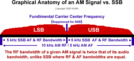
Figure 1
In the example above, a 10kHz I.F. Filter was used resulting in 5kHz of audio response... This is a huge difference in terms of reproducing more natural high frequencies found in human speech. Just remember, that when selecting I.F. filters, remember the filer bandwidth / 2 rule of audio response.
"Flatness" is a term that relates to even or "flat" amplitude across an audio spectrum within 3dB. In our context here, a "flat" device is one that can reproduce the original signal without altering the amplitude of that signal at any given frequency within the desired passband. For example, if a pure "white noise" source, where all frequencies are even in amplitude, is fed into a device like a stereo amplifier, then the stereo amplifier is said to be "flat" if its output faithfully reproduces the white noise source with the same amplitude at any given frequency. See the graph below (Figure 1) for some different flat and non-flat measurements.
Figure 2
White Noise where audio amplitude it equal across the spectrum
Pink Noise where audio amplitude is descending by -3dB/Oct across the audio spectrum
Brown Noise where audio amplitude is descending by -6dB/Oct across the audio spectrum.
Non Flat Radon Receiver Noise where there is "roll-off" on both sides of the audio spectrum.
Note that White, Pink and Brown noise are all versions of flatness since the amplitude decreases in a constant linear fashion unlike the random receiver noise from a non-flat receiver. Notice that except for the random non-flat receiver noise, all of the other plots are a relatively straight or a "flat" line. In the context of our discussions here, we will reference flatness to white noise where all frequencies of concern are represented equally in amplitude within +/-3dB.
With this in mind, very few (if any) AM transmitter would be considered a flat device. There are several reasons for this but without going into that, rest assured that virtually EVERY AM transmitter needs an equalizer to restore flatness or at least something that is close. This is where "Equalization" gets it name. To "Equalize" is to restore the output signal to something that looks like the signal that was fed to the input of a device such as our voice. To put it another way, we want to make the output audio frequency amplitude of the passband equal to what the source audio frequency amplitude was before it was distorted. I will cover more on equalization later in the "The Proper Balancing of Audio Amplitude Equalization Throughout the Voice Spectrum" section.
(2) The Audio Distortion Properties of the Transmitter
The transmitter's ability to reproduce audio with less than 1% THD (Total Harmonic Distortion) with low IMD (Intermodulation Distortion) figures will be very difficult to achieve. This is beyond the scope of what I am writing about here, but every effort should made to keep your transmitter as clean as possible! Also keep in mind that a transmitter that cannot reproduce audio flatness would also be considered a form of distortion, since the resulting output audio frequency amplitude is a distortion of the original audio source.
The audio processing that will precede the transmitter may even aggravate the transmitters distortion specs, so again, great care should be taken when adjusting and aligning your transmitter and pre- transmitter processing.
Know your transmitter's final PEP rating and keep your carrier power at no more than 1/4 of this or less! I will explain more about this later when dealing with "The Percentage of Modulation Used".
(3) The Audio Characteristics of the Microphone
Your microphone selection is not as critical as the transmitter's bandwidth capability, but still worth some consideration. After all, if a microphone cannot reproduce frequencies below 200 Hz or above 3kHz accurately, all of the EQing in the world cannot make up for its deficiencies and the AM audio that you transmit will be limited before it ever has a chance at the transmitter!
(4) The Percentage of Modulation Used
This is a major issue with the AM mode. Since AM is inherently an Amplitude Modulated mode by design, the carrier modulation will be directly proportional to the "Loudness" of the perceived audio relative to the carrier strength.
A nice way to monitor modulation percentage is the use of a "Mod-Monitor" (Modulation Monitor) that reports both positive and negative peak values. An oscilloscope can also be used for this purpose although it is a little harder to interpret positive vs. negative envelope peaks.
If you are looking for a formula designed to calculate positive modulation percentage, and you know the "PEV" (Peak Envelope Voltage) vs. the unmodulated carrier voltage via an oscilloscope, the following formula (Figure 3) was provided by K2WS:
Where:
PEV = Peak Envelope Voltage
Carrier Voltage = Unmodulated Voltage of the Carrier
When an carrier is modulated by 100%, the voltage will double and the power output will quadruple relative to the carrier output.
If we produce a 100w carrier, and the modulation level is at 100%, the peak envelope power is 400 watts. But, the peak envelope voltage max is twice the peak envelope voltage of the carrier alone. So, for example; if the carrier alone produced 20v RF peak to peak, then 100% positive modulation will produce 2 x 20v which equals 40v peak to peak voltage.
Since power changes with the square of the voltage, then the power during 100% positive modulation will increase by the square, so the power increases 2 squared or 4 times! So, 100% positive modulation will produce 2 times the RF voltage and 4 times the RF power.
Using an oscilloscope to measure modulation percentage is achieved as follows:
|
Figure 3

Scope Calibrated for +1 and -1 Divisions
With Full Unmodulated Carrier Applied
Figure 4
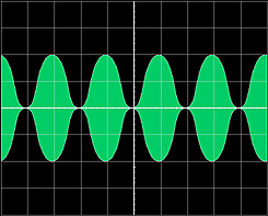
AM at 100% Symmetrical Modulation
Figure 5
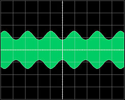
AM Undermodulated
Figure 6a
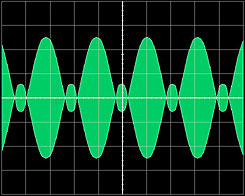
AM Overmodulated (Low-Level)
Figure 6b
AM Overmodulated (High-Level)
Figure 6c
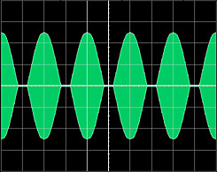
AM Asymmetry - Correct Phase (Pos 110%, Neg 95%)
Figure 6d
AM Asymmetry - Inncorect Phase (Pos 95%, Neg 110%)
An oscilloscope is the best way to measure voltage amplitude. However, if you happen to have a good quality Peak-Reading wattmeter, the formula can be expressed to accommodate PEP instead of PEV as follows:

Using the formula above in an example, if we start with a 100w unmodulated carrier, and with modulation we measure 400 watts PEP with our peak reading watt meter, the math would solve as follows:
Pos Mod % = [(square root of 400 - square root of 100) / (square root of 100)] x 100
Pos Mod % =[(20 - 10) / (10)] x 100
Pos Mod % = [(10) / (10)] x 100
Pos Mod % = [1] x 100
Pos Mod % = 100%
If the carrier is under-modulated, the resulting audio will be light and subdued. On the other hand, if the carrier is over-modulated (above 100% negative peaks), distortion will quickly set in. If the negative modulation peaks can be limited to under 100%, then the positive peaks could be above 100% without distortion! This can ONLY be achieved with asymmetrical modulation. Symmetrical modulation, like a pure sine wave, can NEVER exceed 100% modulation without distortion. Because the human male voice tends to be asymmetrical, we can take advantage of the audio phase orientation where the positive peaks are greater than the negative peaks.
This is where "Asymmetrical Peak Limiting" built into modern AM processing comes in handy! Again, the average male voice is asymmetric in nature. This means that when examined on an audio spectral analyzer, the amplitude peaks will be slightly higher on one side of the plot as opposed to the other. This is why proper "Phasing" of the audio is critical! We always want the positive peaks to be higher than the negative peaks in amplitude since the negative peaks cause distortion when modulated above 100% at the transmitter. There are devices out there called "Phase Rotators" and "Phase Scramblers" that keep the the voice phase positive at all times. However, these devices are not really needed if just one mic and one voice is used. Once the correct phase is established, it will rarely ever change with just one voice and microphone.
With modern AM processing where built in asymmetrical peak limiting is employed, we can manage the negative peaks at about 95% while letting the positive peaks travel well above 100% while still satisfying the transmitter with clean output. It's like having your cake and eating it too! Of course, like anything else, there are some purity issues and tradeoff when using real aggressive peak-limiting. There will always be a fine balance between low distortion and aggressive peak limiting. The trick is finding the balance that will satisfy both sides of the equation - Loudness vs. Cleanness. A little bit of peak limiting will go a long way, so don't get too carried away!
See the Inovonics Model 222 Data Sheet by Clicking Here
(5) The Proper Balancing of Audio Amplitude Equalization
As mentioned earlier, equalization helps restore some flatness to a not so flat signal. The flatter the transmitter can be made to operate naturally, the less need for external equalization processing. Ideally, if a transmitter were perfectly flat within the desired audio passband, say from 100Hz up to around 5~7 kHz, and the microphone being used is flat in the same passband, then theoretically no equalization would be required other than for personal persona and effect. But modifying or building a transmitter with flat audio characteristics can be quite a challenge in some cases. So audio equalization can be a very useful tool in restoring some degree of flatness to a less than flat transmitter.
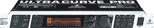
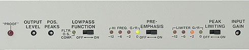
See The Behringer DEQ-2496 Spec Sheet by Clicking Here
I personally like the Behringer DEQ-2496 "Ultra Curve Pro" digital voice processor which not only includes a 31 band
digital 1/3 octave EQ, 10 digital fully programmable parametric EQ's, three fully programmable dynamic EQ's, but also has in its arsenal a great
downward expander, compressor, peak limiter and if that were not enough, a real-time audio spectral analyzer (RTA). For about $300, the Behringer
DEQ-2496 is a great way to gain tons of control over EQ and Dynamics. In combination with the Inovonics 222 AM asymmetrical processor, it is
a killer combination!
If you cant afford an AM processor with built-in pre-emphasis but you would still like to simulate an NRSC 75µs Pre-Emphasis
Curve (seen below in red) using a 1/3 octave EQ, you an achieve this by examining the following graphs and simulated EQ settings that
I have provided below in Figures 7 and 8:
Figure 7
Figure 8
The EQ values used (above) will simulate 75µs NRSC pre-emphasis very nicely!
Note: It should be mentioned that "pre-emphasis" should not be a substitute for your normal speech EQ, but
rather employed in addition to your desired speech EQ, to compensate for the de-emphasis (high frequency roll-off characteristics) of the receiver
that's listening to you.
(6) Amount of Control Over Vocal Dynamics
Dynamics in human speech can approach increases in amplitude by as much as 120dB SPL under certain extreme circumstances such
as yelling, coughing, sneezing or even laughing. On average, these dynamic bursts usually only reach about +50dB to +70dB SPL peak levels. Average
speech (peaks not included) are in the order of +30dB to +50dB depending on your speaking style. Even at low levels of speech, the dynamic content
contained in normal speech is more than any transmitter can handle on its own! This is where vocal dynamic processing (Compressors, AGC Gain
Riders, Peak Limiters, etc...) come to our rescue. They do exactly what is implied by their names; compress or limit the amount of the signal
amplitude coming out as opposed to the signal amplitude that was going in.
If you are familiar with the term "Compression Ratio", it means just what it says; "The Ratio of input amplitude changes vs. output
amplitude changes". For example, a compression ratio setting of 4:1 means that for every 4dB of rise in amplitude at the input of the compressor,
only 1dB of rise will occur at the output of the compressor! Infinity:1 means that no matter what the rising amplitude is at the input, the output
will NEVER change! 1:1 would mean no compression or altering of the dynamics takes place at all so that every dynamic increase of amplitude at
the input will be mirrored at the output.
The problem with conventional analog compression and peak limiting is the slow attack time. When a processor takes even a few milliseconds to
capture the dynamics of a signal in order to reduce those peaks, a phenomena known as "Overshoot" occurs and it's too late to do anything
about it. When viewed on a wave program, the audio compression overshoots look like this in Figure 9:
Figure 9
Audio Compression Overshoots
Notice the spikes at the beginning of each audio envelope. This is caused by the attack delay time as mentioned above. This
phenomena generally sounds like "ticking" and is very annoying to say the least! What is needed to avoid this type of problem is a
"Zero-Attack" compressor or peak limiter. Processors of these types are usually digital with some small "Look-Ahead" feature
that smoothens out the resulting peaks before releasing the signal to the output of the processor. The Behringer DEQ-2496 just happens to offer
zero-attack time with its compressor and peak limiter.
Below (Figure 10) is another processed voice envelope but this time, a "Zero-Attack" time limiter was used:
Figure 10
No Audio Compression Overshoots
Notice this time that there were no overshoots what so ever! This is how you would want the processed envelope to look if viewed
in a wave program.
The two processors mentioned above are excellent choices for those on a limited budget (no pun intended). There are many choices out there when
it comes to choosing compression and peak limiting equipment. But after much research, I have found that these two are the best "bang-for-the-buck"
processors that will not break the bank or get you in too much trouble with your spouse!
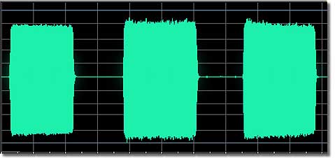
With good EQing, compression and tight asymmetrical peak limiting, even the most outrageous peaks cannot escape, insuring that a constant and
controlled audio signal will be delivered to your transmitter, giving you the freedom to talk the way you want without worrying about excessive
amplitude or distortion as a result of poorly controlled dynamics. See resulting voice envelopes below that employed both zero-attck time dynamic
processing and asymmetrical (negative) peak limiting. Also notice the density improvement with the average envelopes (middle section of the graph)
in Figure 11.
Figure 11
Note: The above graphic was obtained via a "Cool Edit 2000" modulation wave pattern... Not an oscilloscope!
(7) Band Conditions
There is not much we can do about band conditions that cause selective fading, phasing, noise or heterodyne. The best we can do here is to select
our antennas wisely and just deal with the rest. On the receiver side, a well designed synchronous detector could be a great benefit since it
only demodulates one sideband or the other, virtually cutting the QRM in half.
AM Transmitter AF / RF Monitoring
![]() For more on Scope setup and monitoring, see the "Scope
Your Audio Modulation" page...
For more on Scope setup and monitoring, see the "Scope
Your Audio Modulation" page...
There are several ways to monitor your transmitter AM audio. If you are using one of the more modern solid-state transceivers, you may have an
AM monitor circuit built in. However, I have never heard one that can accurately reproduce the actual transmitted audio. If you are using a separate
transmitter and receiver, the quality of your receiver will determine how accurate of an AM signal you will monitor. In either case, these methods
of monitoring your AM transmissions will not produce very satisfying results.
The three best solutions for monitoring your AM transmissions are:
1) Acquire a good quality "Modulation Monitor" - Can be pricey!
2) Acquire a good quality Commercial Receiver - Can be pricey!
3) Purchase or build a simple "RF-Demodulator" / "Diode Detector".
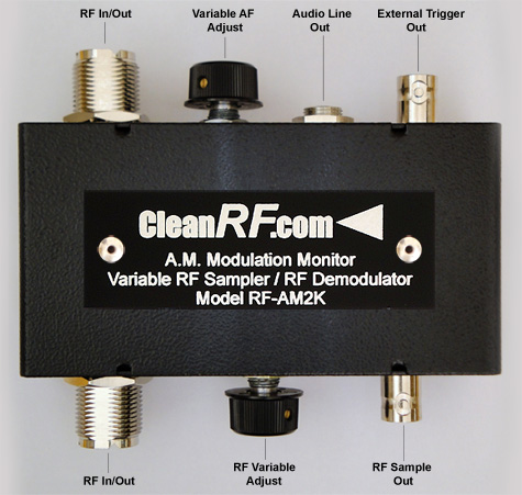
An Excellent and affordable 200 watt AM Modulation Monitor (RF Demodulator) and Variable RF Sampler combo or dedicated high power
2000 watt AM Modulation Monitor can be purchased online or via phone at CleanRF
Technologies. See the products below in Figures 12, 13 and 14:
Figure 12
CleanRF Technologies "RF-D" RF-Demolulator
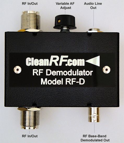
Figure 13
CleanRF Technologies "RF-S2K"
Variable RF-Sampler
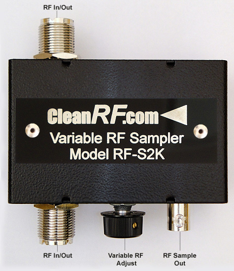
Figure 14
CleanRF Technologies "RF-AM2K"
AM Modulation Monitor / Variable RF-Sampler
The RF Demodulator and Modulation Monitor makes it possible to monitor the transmitter's
demodulated AM audio via a 1/4" TRS jack. This audio output is suitable for either headphones or the line-level input of your stereo amplifier
or mixer.
These boxes are a much better way to monitor your AM demodulated audio signal than any external antenna method since the monitoring occurs
in-line instead of from a constantly varying external RF signal. I also find that there are no proximity 60Hz hum influence problems with these
boxes either!
If there is anything about the RF Demodulator / Modulation Monitor that may be considered a negative, it's the fact that the audio output from
the box is so hi-fi that very few receivers out there will hear you like you hear yourself. To help you get a better perspective on how an
average listener might hear your audio and to somewhat simulate a typical de-emphasized receiver frequency response, you may want to "de-emphasize"
the output audio from the diode detector box by feeding an external EQ and bumping down the high frequencies above 1kHz using a standard 75us
NRSC de-emphasis curve by adjusting your EQ with inverted 1/3 octave cut filter settings as opposed to the 1/3 octave pre-emphasis boost filters
as follows:
2500 Hz (-3dB)
3150Hz (-3dB)
4000Hz (-4dB)
5000 Hz (-6.5dB)
6300Hz (-7.5dB)
8000Hz (-9dB)
The RF Sampler makes it possible to sample RF (via a BNC connector) after your amplifier for oscilloscope modulation envelope
monitoring.
These two devices would be placed in your RF chain as follows in Figure 15:
Figure 15
AM Receiver Audio Processing?
The AM receiver is as critical to a high quality AM audio experience as is the transmitter! Whether or not you will need any external EQing depends on your receiver. And even an EQ may not provide suitable results if your receiver lacks the bandwidth to effectively and accurately reproduce high-fidelity AM signals.
Your best bet is to use a receiver (or transceiver) with sufficient receiver bandwidth to start with. In most cases with modern solid state rigs, you can either make a selection on the front panel to bypass the I.F. receiver filters at will or at least change the AM receiver(s) filters with a 5kHz or more audio passband.
The older "Vintage" equipment can be a little trickier depending on what you are using.
One of the benefits of the Behringer DEQ-2496 processor mentioned in "Point 5" above is its built-in RTA (Real Time Audio Analyzer). With this device you can actually measure your receiver's audio bandwidth capabilities. There are several computer based audio spectral analysis tools available also.
It may be a good idea to find out where your receiver stands in terms of audio bandwidth and flatness. If your receiver is within about 15dB of flatness from 100Hz to 5kHz, then an EQ would prove useful in equalizing the audio. If your receiver rolls-off beyond 15dB of at least a 5kHz audio passband, you may want to consider modifying your receiver, or finding a different one if receiver accuracy is what you are looking for.
Also, receiver distortion may be an issue if it exceeds 10%. This can also be a difficult thing to remedy. All of the processing in the world cannot fix this! Just keep in mind that what you hear from your AM receiver may not be the same as what the transmitting AM stations is really transmitting! Again, the only way to know for sure is by proofing the receiver with some kind of audio spectral analyzer.
For additional reading, see: "Broadcast Chain Tutorial" and "Polycom White Paper" articles.
AM Related Links:
Amplitude Modulation for the 21st Century
The AM Window
AM MP3 Sound Bites(Not Yet Available)
If you would like to send a comment, question, suggestion or point out an error, please use the form on the "Feedback" page or e-Mail me at the address appearing at the bottom of this page.
73,
John Anning, NU9N
| John M. Anning - NU9N
e-Mail: |
Apologetics 1 | Apologetics 2 | Audio Glossary | Donate | eSSB Mods | eSSB Ready Rigs | Transmitter Settings for eSSB
File Downloads | News | Radio Connections | Transmitter Settings | Scope Your Audio | Site Map | Site Search | T-Pad Calculator