NU9N eSSB Flash Into Page
NU9N eSSB Hi-fi Audio
Amateur Radio Extended SSB Hi-fi Mid-fi Lo-fi Audio
 

W3C Validated HTML 4.01 Compliant
W3C validated CSS compliant

Mods - Kenwood TS-870 ACC2 Input
C131 Modification via LB5VA


Mods - Kenwood TS-870 ACC2 Input - C131 Cap Modification
(This mod flattens out the ACC2 audio input low frequency response)


Kenwood TS-870 ACC2 C131 Cap Mod

Disclaimer Notice:

The following modifications were obtained from LA4WAA and should be done by qualified personnel at the owners risk. I am not responsible for any damage to, or illegal operations of the equipment as a result of mod errors or possible mod misinformation via this page.

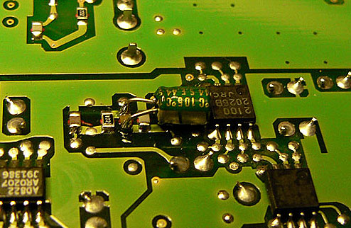
Kenwood TS-870 ACC2 Audio Input - C131 Capacitor Modification:
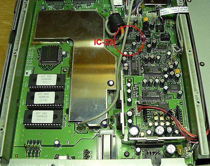
Source courtesy of LB5VA - Original mod by W9AC

It has been documented by several Kenwood TS-870 owners that feeding audio to the ACC2 rear input, instead of the front panel mic input, results in lower distortion audio. This is because some of the speech amplifier circuits are effectively bypassed that are the source of the distortion, especially in the high frequency area above 2kHz.

However, because the ACC2 audio input of the Kenwood TS-870 was designed for data audio (such as that from a TNC using the digital modes), the audio characteristics of the ACC2 audio input are attenuated below about 200Hz.

The following modification addresses this issue by changing the value of the C131 capacitor that the ACC2 audio input travels through, allowing low frequency audio to freely pass through the circuit.


C131 IN THE SCEMATICS:

C131 Schematic
Click to enlarge


C131 Modification Procedure:

  • REMOVE BOTTOM COVER

Kenwood TS-870 Bottom Cover Removed

  • REMOVE METAL SHIELD FROM PCB

Kenwood TS-870 TX/RX Unit Exposed
Click to enlarge

  • REMOVE ALL THE WIRES AND RIBBON-CABLES AND SCREWS FROM PCB
    Look for IC-23 - Capacitor C131 is under the PCB in that area.

  • LOCATE THE CAPASITOR ON THE BACKSIDE
    C131 is on the solder side of the PCB. With a beeping ohm-meter, find the connection from pin 5 on IC-23 to the R137 (1K) witch is under the PCB, to the left of C131 on the picture.

C131 Mod Finished
Click to enlarge

  • SOLDER THE NEW CAPACITOR WITH "PIGGY-BACK" METHOD
    (DO NOT remove the original C131)

    Use a mini 4.7uF/35V from ELFA (67-195-20). This fits nice under the PCB. The positive lead to the direction of IC-23 and the minus lead toward the front, like seen on the picture.

C131 Mod Finished

IMPORTANT PTT NOTICE:
When feeding your rack audio in to the ACC2 jack (pin 11 Audio plus, Pin 12 Audio Shield), you MUST also key the radio from the ACC2 jack (PTT Pin 9, PTT Ground Pin 8) or the audio will not pass. Audio fed into the ACC2 input will NOT pass if you use any PTT method other than the ACC2 PTT pins.


This completes the modification. Have fun!

John M. Anning - NU9N e-Mail:  e-Mail NU9N
Home | Intro | About | Rx | Tx | Extended SSB | AM | Rec/Play | Photos | Feedback | Sites | MP3
Apologetics 1 | Apologetics 2 | Audio Glossary | Donate | eSSB Mods | eSSB Ready Rigs | Transmitter Settings for eSSB
File Downloads | News | Radio Connections | Transmitter Settings | Scope Your Audio | Site Map | Site Search | T-Pad Calculator
eSSB